Blender’s material selection and the light settings
Hi everyone, in this article, we will discuss Blender’s material selection and the light settings.
Hi everyone, in this article, we will discuss Blender’s material selection and the light settings.
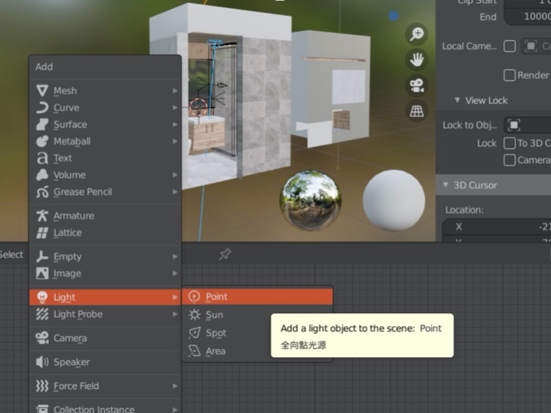
First off, let’s talk about the light source. There are different types of light that can be easily identified on the image.
On the 3DView, press Shift+A, then on the pop-up menu, move the mouse cursor over the “Light” option then you should be able to see a sub-menu appear on the right showing four types of light.

Press M to select a light type and a Collection Manager window will immediately appear. At the bottom of the window, locate and click the “Add Collection” button to create a new collection, which is then given the name called “light”. Click the “Cube” icon right next to the collection name to put all selected light objects into this collection for better management of objects with different properties.
PS: Remember to activate the plugin first. On the toolbar, click Edit → Preferences → Add-ons → Interface and check the Collection Manager option.

At the bottom right, there is an edit pane showing properties of the selected object. Clicking the green bulb icon will show properties of the light object. Relevant parameters can also be modified here. In “Sun”, the light strength ranges from 0.3 to 2 and is approximately 40 for other lights. Depending on the light effects, this number can also be set to 80 or greater than 100.
On 3D View, you can change the light orientation by pressing G (move), R (rotate), S (shrink) or T key on the keyboard. You can also use the functional buttons on the left of 3D View.

Next is the World light.
In the diagram below, the icon at the top left corner, “World” is the environment material in this virtual world as we edit in the Shader Editor window. As shown below, we can also see how the nodes are cascaded, the required I/O and use of the nodes in between. These node cascades give us a clear overview of what affects the image effects so knowing these nodes is very important to designers.
Node creation: Click “Add” at the top to add new nodes or press shift + A keys to show a list on this window.

The orange node in the middle allows you to insert HDRI images. This technique can be used to create the world lights and reflections.
Finally it’s the pink node, which is the world output. Before it, there is a green background node. Connect the background dot to the surface dot of the world output node. Dots only accept inputs from dots with a common color.
The orange node is the image node. Click Add → Texture and select Environment Texture for creating the world environment. On the Environment Texture window, click Open to browse for the image.


Before selecting the environment image, you can first download free HDRI images from hdrihaven (https://hdrihaven.com/hdris/) to a self-defined folder. For example, if the downloaded file name is CGsource, simply save it in the Textures folder of the project. Textures folder is a default folder created by Blender. After opening the Textures folder, select an .hdr or .exr image file to load the image to the node.

When the orange node is clicked, the node edges will turn orange indicating that the node is selected. Press ctrl+t to show the two connected nodes. We will only use the rotation and the z-axis. To rotate the environment image by adjusting the z value, left click and hold down the mouse button then move the cursor left or right along the z bar.

Enable the mirror ball mode, then switch to the computation mode to present the actual environment.

To the left was the preview mode and the default environment balls are at the bottom.

Check Scene World box if you would like to see the background HDR image as a result of the computation.

In order to see the effects resulted from changing the z-axis value, make sure the yellow output dot of the image node is already linked to the input dot of the background node and the background green dot is already linked to the surface dot of the world output node.

The grey dots relate to changing values. The math node can be added by click Add → Converter → Math. The math node is like the overlay blend mode in Photoshop, which enhances the HDR image.

The above are introductions to Blender’s environment and light.
Let’s discuss the object now. First switch to Shader Editor, then click World → Object.

The green node is basically the material node in the Shader. There are many parameters in this node. The orange node is the image node which can be created by either dragging the image from your computer disk to the Shader or clicking Add → Texture → Image Texture to select an image file on the disk.

The two nodes in between orange and green nodes are color adjustment nodes.

Click Add→ Color to add new nodes.
On the Properties pane on the right, click the icon highlighted with a green rectangle to duplicate a material ball. To rename the ball, simply click the texts behind it.

We can link the two material balls together. Of the two material balls, Factor or Fac determines the prominent one. The Checker Texture node corresponds to a checker pattern. 0 and 1 of the Fac value in the Mix Shader node represent total black and white in Checker Texture respectively. Therefore two types of materials are shown on the wall above.

PBR texture refines the result. Eevee is Blender’s realtime render engine which adds simulated light to enhance the result.